Plus current series
Home > Products > Plus current seriesChapter 1 Purchasing Check
This chapter describes the purchase of HK-MTU-T8000P series of intelligent wireless test post need to confirm the content.
1 Overview
2. Check out the box
3. Nameplate data
1.1 Overview
The HK-MTU-T8000P series of intelligent wireless test piles includes two parts of the test pile pile (composite) and the test pile intelligent wireless data remote module, in which the test pile intelligent wireless data remote module is transported in an independent packaging way.
After the test pile is fixed in the field, it can be used to test the installation and testing of the intelligent data remote sensing module. The test pile intelligent wireless data remote module must be installed and configured correctly to meet the design function. Hardwell Automation Technology Co., Ltd. under the guidance of qualified engineers to install.
1.2 out of the box inspection
Products in the factory before the strict inspection, but due to transport or may not be expected to happen, so after the purchase of the product, be sure to carefully check.
| Confirm the project | Confirmation method |
| Whether or not parts are damaged or damaged | Check the overall appearance and check for damage in shipping |
| Screws and other fastening parts are loose | If necessary, check with a screwdriver |
| Brochures, certificates and other accessories | Manual and corresponding accessories |
For safe transport, intelligent wireless test piles are usually required to pack, when you open the box, please keep the packaging materials for future use when the need for transport.
Including the following components:
● HK-MTU-T8000P series test pile pile (composite material) 1
● HK-MTU-T8000P series test pile intelligent wireless data remote module 1 only
● Product accessories (including nameplate, waterproof caps, fixing screws, cable ties, etc.) 1 batch
● 1 part of product manual
● 1 product certificate
1.3 nameplate data
1.3.1 test pile intelligent wireless data remote module nameplate
1.3.2 Test Pile Intelligent Wireless Data Remote Module Model Description
Chapter 2 Installation Wiring
This chapter mainly describes the installation of the equipment size and wiring requirements
1. Installation dimensions are connected to the cable
2. Installation site requirements and management
2.1 installation size and cable connection
2.1.1 test pile intelligent wireless data remote module dimensions;
2.1.3 Connection of cables
Test pile intelligent wireless data remote module used
Waterproof cable direct connection, cable specifications:
4 core * 0.5mm2 waterproof cable.
The interface definition and connection line of the signal cable are shown in the following diagram:
| Signal acquisition cable terminal | |||
| Line number | Signal name | Wiring instructions | Remarks |
| CN1 | pipeline | Connected to the pipe | |
| CN2 | Reference electrode | Connected to the reference electrode or to the reference electrode of the polarizing probe | |
| CN3 | Polarized electrode | And the polarized probe in the polarization plate connected | This terminal is the same potential |
| CN4 | Polarized electrode | And the polarized probe in the polarization plate connected | |
2.1.4 Power supply
Test pile intelligent wireless data remote module using a high-performance lithium battery as a power supply, in order to adapt to the complex application environment, improve the stability of the system, the module uses advanced power management technology, great Extending the power cycle of the powered battery pack.
2.2 Installation site requirements and management
Please install this product in the vicinity of the pipeline and fill the inside of the test pile with cement for reinforcement of the pile. If the intelligent wireless data remote module and special antenna in the test pile are submerged in the water for a long time, Normal work, but also lead to wireless signals can not be fired.
2.2.1 installation site
The installation site should meet the following conditions:
N Ambient temperature -40 ℃ - + 60 ℃;
N try to avoid high temperature and humidity, humidity less than 90% RH, no rain dripping;
Do not install on flammable objects such as wood;
N No flammable, corrosive gases and liquids;
N installation base is solid without vibration;
N No electromagnetic interference, away from interference sources;
Chapter 3 Technical parameters
This chapter mainly describes the technical parameters of the test pile intelligent wireless data remote module.
1. Module function
2. Technical parameters
3.1 module function
[GPRS section]
Support dual frequency GSM / GPRS
N supports 800 / 1900MHz dual frequency
N real time clock
【Bluetooth】
N Working frequency band 2.4GHz
N Bluetooth protocol V4.0 BLE
N Sensitivity -93dBm
N Communication distance 20m
【GPS Beidou module】
N Level accuracy 2m
N channel: 72 search channel
N Sensitivity -167dBm
Enhancements:
Transparent data transmission and protocol conversion
N Data terminal is always online or operating mode selection
N support virtual data private network
N support RS-485 interface
N Optimize the electromagnetic compatibility design, suitable for electromagnetic environment and the requirements of high application requirements
N The use of advanced power technology, power supply to adapt to a wide range of equipment to improve the stability
3.2 Technical parameters
Test pile intelligent wireless data remote module main technical indicators:
Sampling parameters:
Power supply potential
Power off
n Ambient temperature
n Ambient humidity
n Geographic information
Interface:
n Antenna interface 50 / SMA / female head
n Serial data interface
v Type: RS-485
v Data rate: 300 ~ 115.200bits / s
v Interface terminal: Standard USB interface
powered by:
n Battery voltage: + 7.2VDC, ripple less than 300mV
n Battery capacity: 56AH
Power consumption:
n communication: an average of 500mA
n Idle when: 20uA
Safety performance:
n Input impedance: ≥ 100MΩ
n Lightning protection: reference potential input with anti-lightning protection
n Insulation resistance: Insulation resistance of reference line and housing, zero line and housing> 10MΩ
n anti-AC interference: anti-AC interference voltage 30VAC
n power strength: 1500V, which lasted 1min
Chapter 4 Installation of Intelligent Wireless Test Pile
This chapter introduces the structure and installation method of intelligent wireless test pile.
1. Intelligent wireless test pile pile body method
2. Intelligent wireless test pile pile debugging steps
3. Intelligent wireless test pile module installation and commissioning
4.1 Intelligent wireless test pile pile structure
The intelligent wireless test pile pile is made of composite material (resin + high strength glass fiber), its external dimensions and color, meet the requirements of the China Petroleum and Natural Gas and Pipeline Branch on the mileage pile / test pile, the appearance of Figure 4- 1:
4.2 Embedded method of intelligent wireless test pile
The test pile pile placement at the bottom of the placement of cement fixed, and placed in which Ф50 PPR tube (for the laying of the signal cable), until the cement solidification, and then the upper part of the test pile with soil fill, The pile size of the test pile is shown in Fig. 1:
4.3 test pile intelligent wireless data remote module installation and debugging
When installing the wireless data remote module in the field, follow the steps below:
1) Cable handling:
The wireless data remote module on the signal cable sheath, from the root stripping 50mm, dotted line with a waterproof tape wrapped, as shown in Figure 2;
Each signal line stripped 25mm, as shown in Figure 2;
The pipe connecting cable stripping about 12mm, and retain the diameter Φ4mm within, please spare part (broken line) cut off, as shown in Figure 3;
The reference electrode line stripped about 12mm;
2) Cable connection:
The "brown" line in the wire is connected to the reference electrode cable and fixed with a brown waterproof cap with a neutral waterproof glue, and the waterproof cap and waterproof glue should be completely wrapped in the cable exposed;
The "blue" line in the wire is connected with the pipe connecting cable and fixed with a yellow waterproof cap with a neutral waterproof glue, and the waterproof cap and waterproof glue should be completely wrapped in the cable exposed;
Connect the "black" wire in the wire to the polarized electrode 1 in the polarizing probe, connect the "gray" wire in the wire to the polarized electrode 2 in the polarizing probe, and connect the neutral " Yellow waterproof cap fixed firmly, and waterproof cap and waterproof plastic should be completely wrapped cable exposed.
3) Cable fixing:
Will be connected to the completion of the cable, 50mm from the joint, with a plastic strapping fixed firmly, placed in the test pile body;
4) Power on module:
The power switch on the wireless data remote module placed in the "power" state, the module will automatically enter the work mode;
5) Equipment commissioning:
Open the intelligent cathodic protection management platform mobile client, enter the field device management options, through the Bluetooth and device communication to see whether the data collected by the device is accurate, and the device location information uploaded to the network platform.
6) Fixation with pile:
Will be completed after the completion of the steps of the red side of the cap and the pile connection in the pile and pile cap overlap at the four sides near the edge of 20mm, drill a Φ3.5mm hole, and M4 tapping screws fixed, as shown in Figure 5;
7) Fixed nameplate:
On the side of the pile, from the center of the upper end face of 100mm, fix the pile nameplate, and fill the pile number with the oil signal pen (see the packing number on the packing box), as shown in Figure 6;
Chapter 5 Operating Instructions
This chapter describes the test pile in the use of intelligent wireless data remote module description:
1. Instructions for using the mobile client
5.1 Mobile client instructions
Test pile intelligent wireless data remote module is intelligent data acquisition and communication terminal, when the test pile intelligent wireless data remote module installation is complete, the power switch can be used, the normal operation without user intervention, to facilitate the user's Installation and testing.
Of course, the user's use of the process in order to query the operation of the acquisition module, or modify its internal configuration parameters, through the mobile client, to achieve the parameters of the query and modify the work.
5.2 Description of the mobile client interface
1) User login interface
When you click into the Kazakhstan control technology mobile phone client, the user interface will automatically enter the user login, as shown in the right: enter the user name and password into the APP user interface
2) Operation interface Main menu
The main menu interface includes: device management, data center, site management, location navigation, evaluation analysis, curve graphics, system settings a total of seven interface;
Chapter 6 Abnormal diagnosis and routine maintenance
This chapter describes the HK-MTU-T8000P series test pile intelligent wireless data remote module in the use of abnormal diagnosis
1. Fault content and processing
2. Daily inspection and regular maintenance
When the HK-MTU-T8000P series test pile intelligent wireless data remote module failure occurs, the module will stop output, the network server will not be able to receive the measured data sent back. When the fault occurs, through the mobile client to read the test pile intelligent wireless data remote module in the state parameters and fault code, the correct reasons to determine the fault and provide appropriate solutions.
6.1 fault content and processing
| malfunction Code | Content | Description | Dealing with countermeasures |
| 01 | Reference potential overvoltage | The reference potential measurement is higher than the internal setpoint | Check long-term reference, pipe connection and external circuit is normal |
| 02 | Reference potential undervoltage | The reference potential measurement is below the internal setpoint | |
| 03 | SIM card error | No valid SIM card detected | Check whether the SIM card arrears Check if the SIM card is securely installed |
| 04 | The server can not connect | The server has an exception | Notify the server maintenance personnel to maintain |
| 05 | wrong user name or password | The server password is incorrect | change Password |
| 06 | The server connection timed out | Within 1 minute, the server did not respond | The server is busy and the phone client will try to connect again after a few minutes |
6.2 Routine inspection and regular maintenance
In the HK-MTU-T8000P series test pile intelligent wireless data remote module in the normal use of the process, need to do routine and regular maintenance checks to ensure its stable and safe operation.
| Check item | check contents | Check cycle | Inspection Method | Judgement standard | Abnormal countermeasure | |
| daily | A year | |||||
| Equipment surroundings | Please check the ambient temperature and humidity | ◎ | Measured with a thermometer and hygrometer | Temperature, humidity limit | Improve the site environment | |
| Whether there is accumulation of flammable materials | ◎ | Visual | No foreign body | |||
| Whether the installation location is immersed in water | ◎ | Visual | No immersion | Improve the installation environment | ||
| device installation | Is the housing installed secure? | ◎ | Visual touch | No abnormally loose | Reinforcement | |
| The internal battery pack capacity of the device | Whether the battery pack capacity is normal | ◎ | Hand-held terminal detection | Rated battery capacity | Replace the battery pack | |
| Equipment terminal fixing screw | Whether the locking part is loose | ◎ | Visually, with a screwdriver to check if the screws are loose | No abnormality | Lock or repair | |
| Whether the terminals are damaged | ◎ | |||||
| ◎ | ||||||
| Equipment cable | Whether Whether there is a clear rust stateit is deformed, skewed | ◎ | Visual | No abnormality | Replacement or repair | |
| Wire sheath is damaged | ◎ | |||||
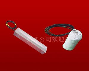 Magnesium alloy sacrificial anode
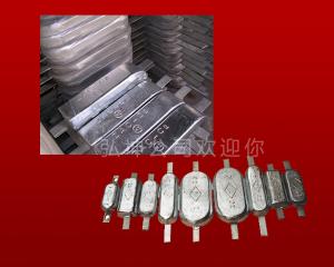 Zinc alloy sacrificial anode
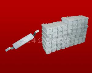 Aluminum alloy sacrificial anode
 Magnesium ribbon
  Zinc belt
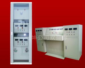 constant potential rectifier
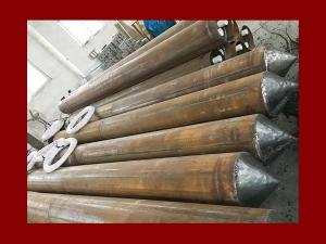 Deep well anodes
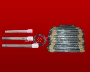 High silicon cast iron anodes
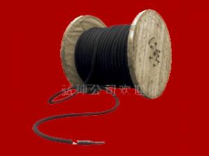 Flexible anode
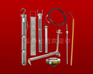 MMO anode
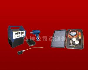 Cathodic protection of copper welding machine
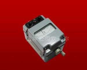 Ground Resistance Tester
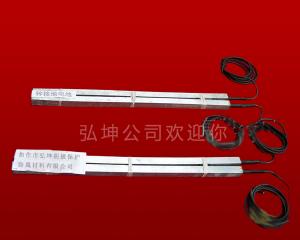 Zinc grounded battery
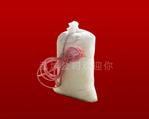 Zinc reference electrode
 Fill in the package material
 Aluminum heat flux
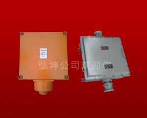 Explosion-proof junction box
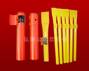 Test piles
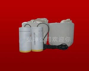 Long - acting copper sulfate reference electrode
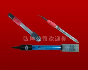 Silver / silver chloride reference electrode
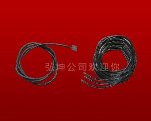 Cathode protection cable
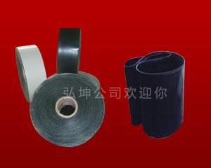 Heat shrinkable tape
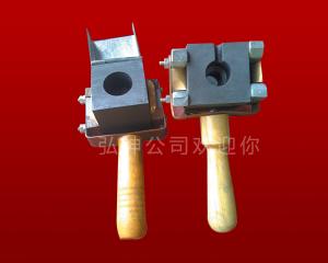 Aluminum heat welding mold
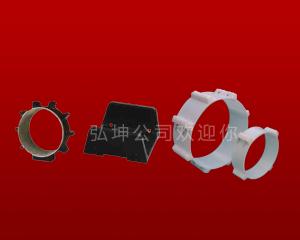 Insulation bracket
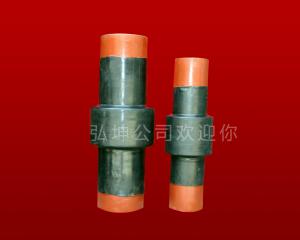 Insulated joints
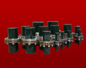 Insulated flange
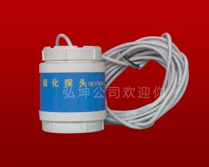 Polarization Probe
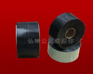 Anticorrosion tape
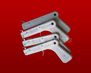 Point guns
 Injury tablets
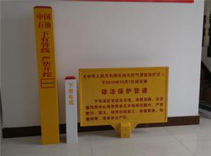 Logo pile
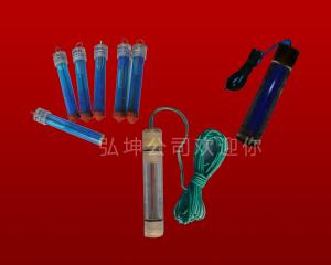 Portable reference electrode